A single low-quality electronic component can cause an entire PCB to fail in the field. In many cases, the issue is not the PCB design itself — it is an unverified capacitor, counterfeit IC, damaged connector, or out-of-spec resistor that passed unnoticed during sourcing or assembly.
Electronic component testing helps engineers identify failures before production, reduce rework costs, improve product reliability, and avoid unexpected field returns. In this blog, you will learn how professionals test electronic components, what failures they look for, and which validation methods actually matter in real manufacturing environments.
Why Electronic Component Testing Matters More Today
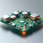
Modern PCBs are smaller, faster, and more complex than ever. At the same time, global supply chain pressure has increased the risk of counterfeit parts, inconsistent quality, and sourcing substitutions.
Even experienced teams now face reliability problems caused by components that technically “match the datasheet” but fail under real operating conditions.
Common issues seen in production:
- Counterfeit ICs with relabeled markings
- Capacitors failing under thermal stress
- Moisture-damaged components during storage
- Incorrect component tolerances affecting signal integrity
- Poor solderability causing intermittent failures
- Batch-to-batch inconsistency from alternate suppliers
These problems rarely appear during visual inspection alone. Proper testing is what prevents hidden defects from reaching assembled products.
What Electronic Component Testing Actually Means
Electronic component testing is the process of verifying whether a component performs correctly before it is used in PCB assembly or final product manufacturing.
The goal is not only to confirm functionality but also to validate reliability, authenticity, and production readiness.
Testing usually includes:
- Visual inspection
- Electrical parameter verification
- Dimensional validation
- Functional testing
- Environmental stress testing
- Solderability analysis
- Counterfeit detection
Different products require different testing depth. A consumer IoT device and a medical monitoring board do not follow the same validation process.
Start with Incoming Component Inspection
Most reliability problems start at incoming material level. If poor-quality components enter production, downstream testing becomes more expensive and less effective.
Incoming Quality Control (IQC) is the first defense layer.
Key checks performed during IQC:
- Manufacturer label verification
- Date code validation
- Packaging condition inspection
- Moisture sensitivity level (MSL) check
- Reel and tray damage inspection
- Quantity verification against BOM
- Surface oxidation inspection
Experienced inspection teams also compare physical markings against original manufacturer references because counterfeit parts often use inconsistent fonts, textures, or laser markings.
A component may look acceptable under normal lighting but reveal remarking evidence under magnification.
Visual Inspection Is More Important Than Most Teams Assume
Visual inspection is often treated as a basic step, but many field failures can be traced back to visible defects that were missed during intake.
This step helps identify handling damage, contamination, and counterfeit indicators before electrical testing begins.
Inspectors usually look for:
- Cracked packages
- Bent leads or pins
- Corrosion or oxidation
- Surface scratches
- Burn marks
- Improper labeling
- Lead coplanarity issues
- Resin inconsistencies
For BGA or fine-pitch components, microscopes are typically required because defects are too small for standard inspection methods.
One overlooked issue in real production environments is component storage damage. Moisture exposure can create internal package cracking during reflow, even when the external surface appears normal.
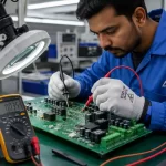
Electrical Testing Validates Actual Performance
A component can pass visual inspection and still fail electrically. This is why electrical testing remains one of the most critical validation stages.
The purpose is to confirm that measured values stay within acceptable operating limits.
Typical electrical tests include:
- Resistance measurement
- Capacitance verification
- ESR testing
- Leakage current testing
- Inductance measurement
- Forward voltage testing
- Continuity testing
- Current consumption analysis
Common tools used:
- Digital multimeters
- LCR meters
- Oscilloscopes
- Curve tracers
- Semiconductor analyzers
For ICs, engineers often validate:
- Power rail behavior
- Input/output response
- Communication protocol stability
- Thermal behavior under load
This becomes especially important in high-speed, RF, industrial, or medical applications where minor electrical deviations can affect system-level reliability.
Functional Testing Helps Detect Real-World Failures
Electrical values alone do not always reveal reliability issues. A component may meet nominal specifications but fail under operational conditions.
Functional testing verifies how components behave inside actual circuit environments.
Typical functional validation includes:
- Power cycling tests
- Load testing
- Thermal operation testing
- Signal integrity observation
- Interface communication checks
- Startup behavior analysis
- Noise sensitivity evaluation
This stage often exposes failures related to:
- Marginal timing behavior
- Thermal instability
- Voltage fluctuations
- Intermittent communication errors
In embedded systems, some failures only appear after extended operation or repeated thermal cycling. These issues are difficult to identify through static measurements alone.
Counterfeit Components Are a Growing Reliability Risk
Counterfeit electronic components are now a major industry concern, especially during supply shortages or urgent sourcing cycles.
The challenge is that counterfeit parts are becoming harder to detect visually.
Common counterfeit indicators include:
- Sanded package surfaces
- Reprinted date codes
- Incorrect manufacturer logos
- Different die sizes internally
- Inconsistent lead finish
- Recycled components sold as new
Advanced verification methods include:
- X-ray inspection
- Decapsulation analysis
- Acetone solvent testing
- Scanning acoustic microscopy
- Die comparison analysis
High-reliability sectors like aerospace, healthcare, and industrial automation typically apply stricter authentication procedures because field failure costs are significantly higher.
Environmental Testing Reveals Long-Term Reliability Problems
Some components function correctly during initial testing but fail after environmental exposure.
Environmental testing helps simulate real operating conditions before deployment.
Common stress tests include:
- Thermal cycling
- High-humidity exposure
- Burn-in testing
- Vibration testing
- Thermal shock testing
- ESD testing
These tests help identify:
- Material expansion issues
- Internal bond wire failures
- Solder fatigue risks
- Package sealing weaknesses
- Heat-related parameter drift
In industrial electronics, temperature variation alone can expose weaknesses that never appear during room-temperature validation.
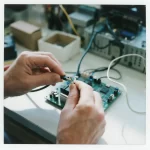
Solderability Testing Prevents Assembly Defects
A component with poor solderability can create intermittent PCB failures even when the component itself is electrically functional.
This problem is common with:
- Aged inventory
- Improperly stored reels
- Oxidized leads
- Reclaimed components
Solderability testing checks whether component leads properly bond during PCB assembly.
Typical methods include:
- Dip-and-look testing
- Wetting balance testing
- Reflow simulation testing
Poor solder joints often lead to:
- Weak mechanical bonding
- Cold solder joints
- Increased electrical resistance
- Field vibration failures
In many production environments, solderability issues are discovered only after assembly defects begin increasing.
Why Component Testing Should Match Product Risk Level
Not every PCB requires the same testing depth. Over-testing low-risk products increases cost, while under-testing critical systems creates reliability exposure.
Testing strategy should align with:
- Product application
- Safety requirements
- Production volume
- Regulatory expectations
- Environmental conditions
- Failure consequences
For example:
Consumer Electronics
Typical focus areas:
- Cost optimization
- Basic functional verification
- Standard electrical testing
Industrial Systems
Additional focus areas:
- Thermal reliability
- Long operational life
- Vibration resistance
Medical Electronics
Higher validation depth:
- Traceability requirements
- Extended reliability testing
- Strict supplier validation
The testing process should always reflect actual field conditions rather than theoretical specifications alone.
Common Mistakes That Reduce PCB Reliability
Many PCB reliability issues are caused by process shortcuts rather than engineering limitations.
Common mistakes include:
- Skipping incoming inspection
- Trusting datasheets without validation
- Mixing component batches
- Using unauthorized distributors
- Ignoring storage conditions
- Performing only sample-based electrical checks
- Overlooking solderability degradation
Another major issue is assuming prototype success guarantees production stability. Some component failures only appear at scale or after long operational cycles.
Reliable manufacturing depends on repeatable validation processes, not isolated successful builds.
How Engineers Build a Practical Testing Workflow
Effective testing workflows focus on risk reduction, not unnecessary complexity.
Most reliable workflows follow a layered validation approach.
Typical process structure:
Step 1 — Supplier Verification
- Validate sourcing authenticity
- Review certification documents
- Confirm approved vendor status
Step 2 — Incoming Inspection
- Perform visual and dimensional checks
- Verify packaging and traceability
Step 3 — Electrical Testing
- Measure key electrical parameters
- Compare against datasheet tolerances
Step 4 — Functional Validation
- Test operation inside real circuit conditions
- Monitor thermal and signal behavior
Step 5 — Reliability Screening
- Apply stress testing where required
- Validate long-term operational stability
This layered approach reduces failure risk significantly compared to relying on final assembly testing alone.
Key Takeaways
Electronic component testing is not just a quality step — it directly affects PCB reliability, manufacturing stability, and long-term product performance.
Important points to remember:
- Visual inspection alone is not enough
- Electrical validation helps detect hidden defects
- Functional testing reveals real operating failures
- Counterfeit components remain a serious industry risk
- Environmental testing improves long-term reliability
- Solderability issues can create intermittent PCB failures
- Testing depth should match product criticality
- Incoming inspection is one of the most important reliability stages
Reliable electronic products are usually the result of disciplined validation processes, not luck during assembly.
As PCB complexity continues increasing, component testing will become even more important for reducing field failures, improving manufacturing consistency, and protecting long-term product reliability.
Frequently Asked Questions
Why is electronic component testing important?
Electronic component testing helps prevent PCB failures, improve product reliability, and identify defective or counterfeit parts before assembly.
What are the most common electronic component testing methods?
The most common methods include visual inspection, electrical testing, functional testing, and solderability testing.
How does component testing improve PCB reliability?
Testing helps detect weak or damaged components early, reducing production defects, rework costs, and long-term field failures.
What causes electronic components to fail in PCBs?
Common causes include overheating, poor solder joints, counterfeit parts, moisture exposure, voltage stress, and improper handling.